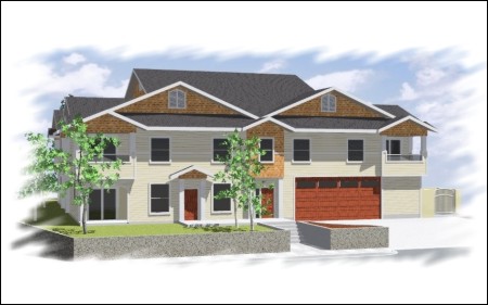
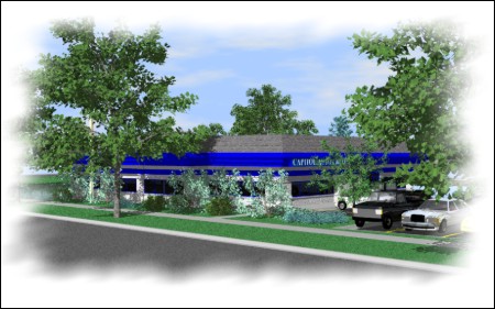
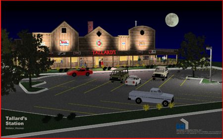
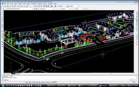
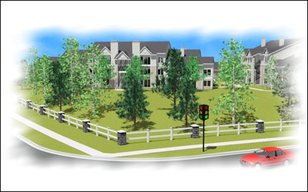
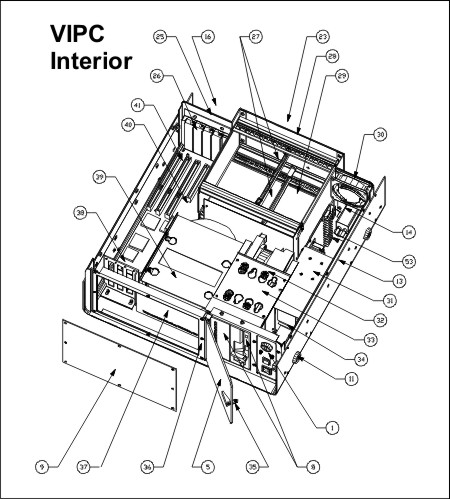
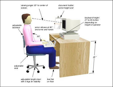
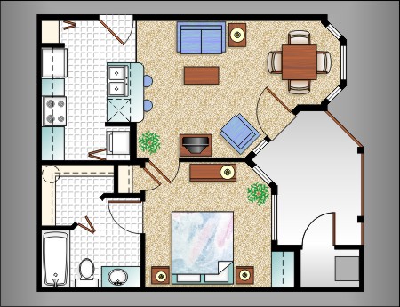
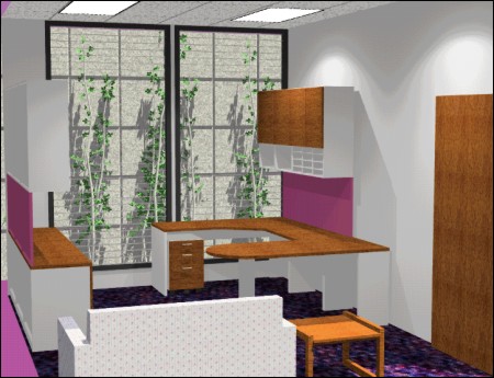
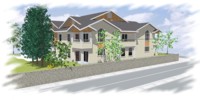
Each of the renderings displayed below was created by building a 3D model of the scene in AutoCAD, rendering the model in AccuRender, and composing the resulting image in CorelDRAW. The 2D illustrations were also done in CorelDRAW using geometry imported from AutoCAD as a starting point. |
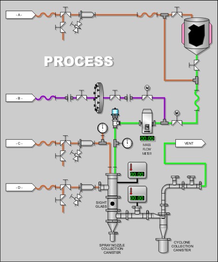
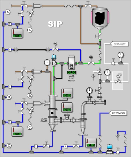
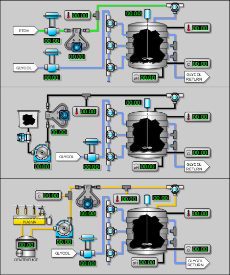
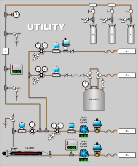
Plant/Process Design Illustrations
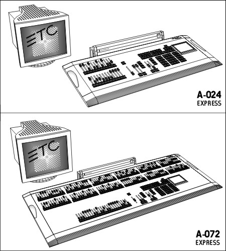
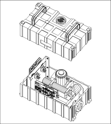
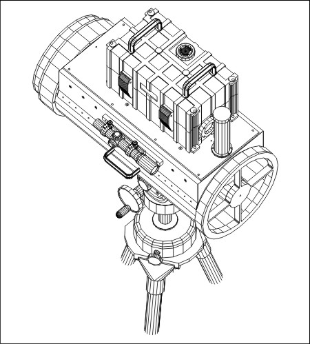
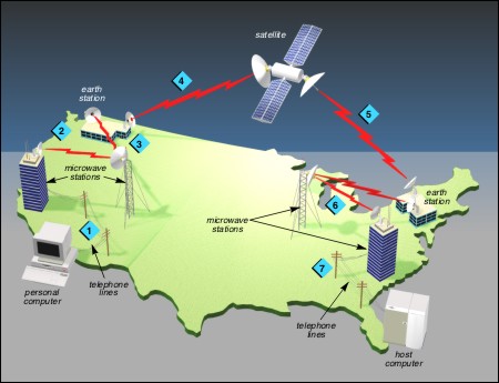
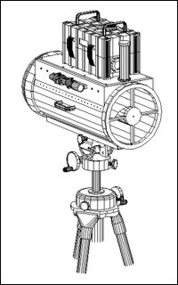
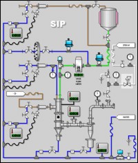
The starting point for each of the diagrams below was an AutoCAD P&ID schematic. To make the component graphics (pumps, tanks, valves, etc.), we created the geometry for each item in AutoCAD using its engineering datasheet as a guide, then replaced the symbolic representations of each component in the schematic with its pictorial counterpart. The completed diagram was then brought into CorelDRAW for graphical styling to produce the finished illustrations. |